Hy-Bridge
Robot-assisted 3D printing and fiber winding footbridge.
Covered by Dezeen on Nov. 29, 2019.
OVERVIEW
TIMELINE
MY ROLE
TEAM
ADVISOR
Combinations of different materials can bring architectural designs to the next level. Inspired by the ICD-ITKE Research Pavilion in 2013-2014 featuring robotic arms as the main fabrication method, our team in Shanghai DigitalFUTURES 2019 completed this project with high efficiency and creativity. 3D-printed metal and composite fibers are applied to serve different structural functions: compression and tension. Two robotic arms are leveraged to complete the fabrication process of fiber winding and metal printing. We researched how robotics might improve the process of fiber fabrication and its corporation with human power.
Mar. 2019 - Jul. 2019
Robotic Fabrication Designer
Material Experiment, Fiber Syntax, Handrail & Step Design
Collaborating Designers:
Xing Hao, Xiaofei Hong, Zongsheng Yu
Philip F. Yuan, Wenhan Li, Liming Zhang
BACKGROUND
WHY FIBERS & METAL?

Concrete is the most widely used material in construction. However, its heavyweight, long fabrication time and low specific strength bring about efficiency disadvantages and require a high cost of labor and time.
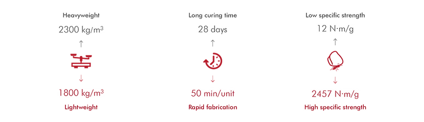
Composite fiber is a novel material used in aerospace manufacturing for its high specific tensile strength. Its material potentials in architectural structure with 3D-printed metal can be further explored applying robotic fabrication.

MULTI-OBJECTIVE OPTIMIZATION
FRAMEWORK

MATERIAL & STRUCTURAL RESEARCH
BIOMIMETIC PROTOTYPES
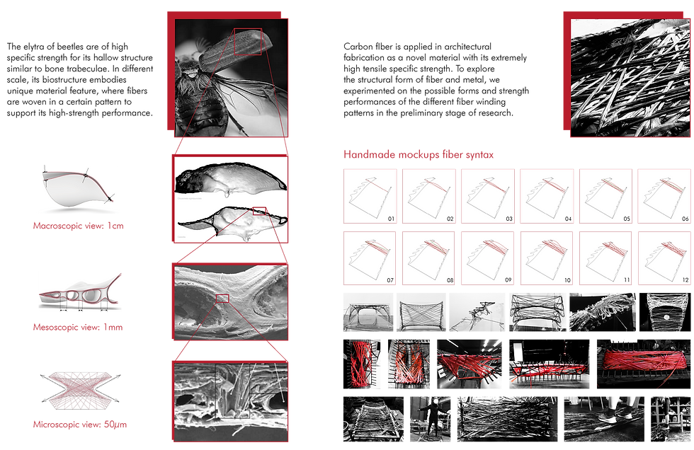
Fiber Simulation Mockups
Inspirations from Elytron
*
*
*
*Picture Resources: https://www.icd.uni-stuttgart.de/projects/icditke-research-pavilion-2013-14/
STRUCTURAL DESIGN
Form Finding & Structural Optimization
Deformation Simulation & Declension

COMPONENT DESIGN
STEP ARRANGEMENT

MAIN STRESS LINES ANALYSIS

SYNTAX OPTIMIZATION
Handrail Fiber Pattern Generation
Segmentation for Assembling

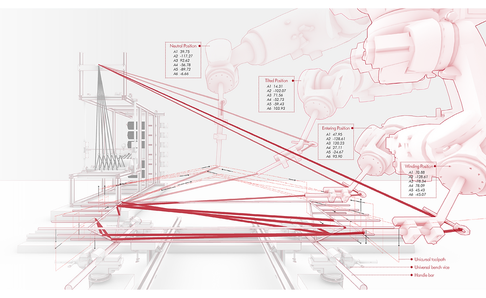
FABRICATION PROCESS
FABRICATION CHALLENGE
3. Tension Control
Unhardened resin reduces the friction between the fiber and the frame as well as the end effector. Extra tension is required to tighten the fibers during the winding process.

4. Unicursal Syntax
The stress lines are straightened into geodesic lines on the frame surface. Fiber syntax should be designed for the robotic arm to wind in a single-thread pattern.

2. Collision Avoidance
End-effector is prone to collide with the anchors on the frame due to accumulative errors. End effectors of different sizes were tested before the actual fabrication.

1. Rotation Constraints
Each axis of the robotic arms is constrained within -360° to +360°. Toolpath should be planned to rewind to the origin after a single iteration.

RESIN BATH SYSTEM DESIGN

Model credited to: Liu Gong, Fab-Union
ASSEMBLING


REFLECTIONS

Collaborate with the machines, instead of operating them.
Discover the potential of the tools and human-power at hand. According to the preliminary material research, the optimal structural performance of fiber prototypes is presented with filament winding. However, a turn-table was required to complete such a winding process, which is unachievable in our lab with only robotic arms. Therefore, we combined the advantages of human-power and machines to manipulate the winding process.
Our Team!

Base hypotheses in an industrial setting.
Be realistic when walking out of the lab. It was very tempting to propose numerous design alternatives when creating material mock-ups because of the generous funding of the lab. But after the completion of this project, I have been thinking - how carbon fibers might integrate with 3D metal printing in the manufacturing industries and bring actual lucrative?